
Search News
Industry Portal
Popular Tags
Why Do Motion Control Systems Lose Positioning Accuracy?
Author
Marcus Torque
Time
Oct 24, 2026
Pageviews
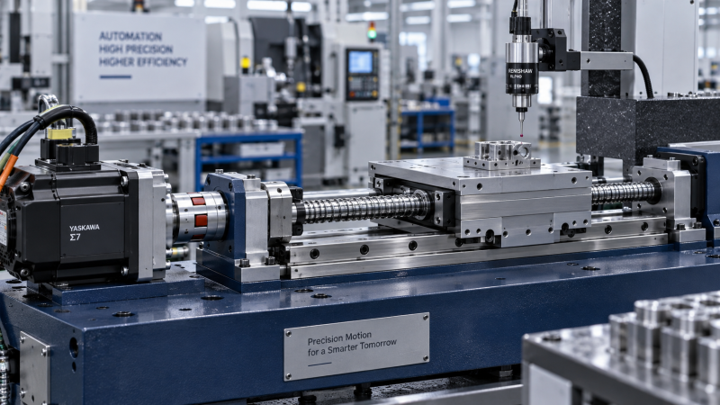
Why Do Motion Control Systems Lose Positioning Accuracy?
Why does motion control lose positioning accuracy? When a production line starts missing tolerances, the cause is rarely limited to a single component. Backlash, thermal expansion, encoder errors, poor servo tuning, and changing loads can all undermine precision—even when individual devices appear to operate normally. Identifying the source of error is essential to preventing scrap, downtime, and unnecessary upgrades.
The difficult part is that a servo drive can report “in position” while the tool, carriage, or workpiece is somewhere else. The controller only knows what its feedback system measures. Anything outside that measurement path—gearbox clearance, frame deflection, fixture movement—can remain invisible. Effective troubleshooting therefore starts with the complete motion chain, not the motor specification.
Define the error before changing the machine
Positioning accuracy describes how closely an axis reaches its intended physical position. Repeatability describes how consistently it returns to a position under specified conditions. A machine can be highly repeatable yet consistently stop at the wrong location. That distinction matters: a stable geometric offset may be suitable for calibration, while inconsistent movement usually requires investigation of mechanics, feedback, or operating conditions.
Also separate endpoint accuracy from accuracy during motion. A dispensing axis may reach its final coordinate correctly but deviate along the path. A packaging mechanism may move accurately yet arrive too late relative to a conveyor. Static positioning tests will not necessarily reveal contouring error, synchronization problems, or excessive settling time.
Write down where the error is measured, whether the axis is moving or stationary, the approach direction, payload, speed, and machine temperature. Without those conditions, a statement such as “the axis is inaccurate” is too vague to support a useful corrective action.
Mechanical errors often sit beyond the encoder
Backlash is especially visible when an axis reverses direction. Clearance in gears, screw assemblies, couplings, or bearings allows the motor to move before the load follows. If feedback comes from a motor-mounted encoder, the drive may record the commanded rotation even though the carriage has not completed the expected displacement.
Compare approaches to the same target from opposite directions. A repeatable direction-dependent difference suggests backlash, frictional hysteresis, or another reversal-related effect. It does not identify the faulty component by itself. Inspect the transmission, bearing supports, coupling connections, and lubrication before assuming a software backlash setting will solve the problem.
Compliance creates a different pattern. Belts stretch, shafts twist, robot joints deflect, and machine structures bend under force. The position error may increase with acceleration, process force, or payload. A system that performs well during an unloaded acceptance test can miss tolerances during pressing, cutting, or handling a heavier part.
Preload and stiffness are not free improvements. Increasing preload may reduce clearance but raise friction, heat generation, and bearing load. The right intervention depends on the assembly design and manufacturer limits, not simply on making every connection tighter.
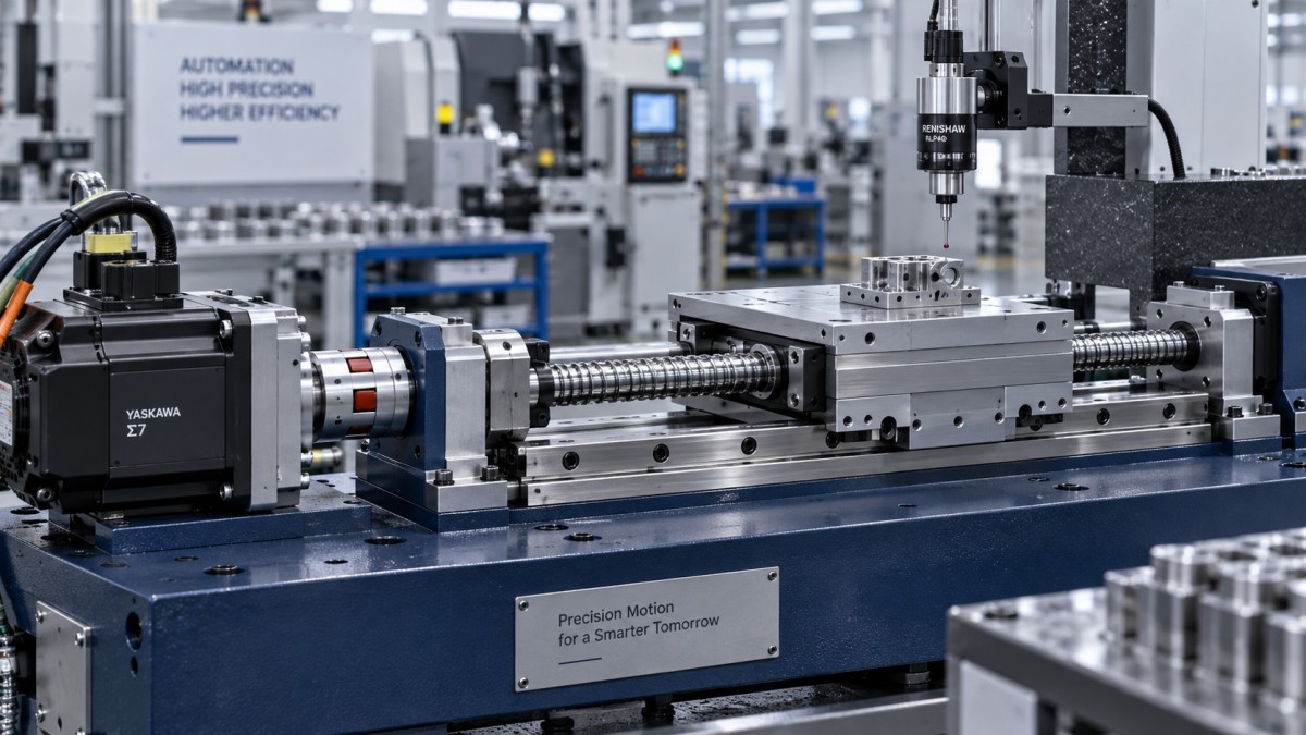
A useful motion-chain diagram places the command, motor encoder, coupling, transmission, carriage, fixture, and actual measurement point in sequence. Marking the feedback location makes it easier to see which mechanical errors the controller can detect—and which require independent measurement.
Temperature changes the geometry
Ball screws, rails, frames, and fixtures expand as their temperatures change. Uneven heating can also distort alignment rather than merely increase overall length. A cold machine may pass inspection and drift after sustained operation, especially when the drive, bearings, or process introduce heat locally.
For a uniformly heated, unconstrained component, linear expansion can be estimated from its length, temperature change, and material expansion coefficient. Real assemblies are more complicated because supports, constraints, and temperature gradients affect the resulting displacement. Measure the operating temperature profile before building a compensation model.
A controlled warm-up routine may improve consistency, but it is not proof that the underlying thermal error has disappeared. Validate accuracy over the production duty cycle, including idle periods and restarts.
More encoder counts do not guarantee more accuracy
Encoder resolution is the smallest reported increment; encoder accuracy concerns how closely that reading represents the actual position. Higher resolution can improve measurement granularity without correcting scale errors, mounting eccentricity, interpolation errors, or transmission deformation.
Check the entire position conversion. Electronic gearing, screw lead, gearbox ratio, engineering units, and coordinate offsets must agree. A scaling mismatch often produces an error that grows with travel. Incorrect homing or a shifting reference sensor can instead produce an offset after startup while subsequent moves remain repeatable.
Electrical interference and feedback integrity also deserve attention. Poor shielding, unsuitable cable routing, damaged connectors, or grounding problems can disturb signals. Depending on the interface and fault detection, the result may be an alarm, intermittent feedback disturbance, or a position discrepancy. Do not assume every accuracy problem caused by noise will appear as a clean, repeatable drift.
Direct load feedback, such as a linear encoder on a carriage, can expose errors hidden from a motor encoder. However, converting to a fully closed-loop arrangement requires suitable control architecture and tuning. Transmission flexibility, backlash, and measurement placement still affect stability and tool-point accuracy.
A servo can be stable but still miss the process requirement
Poor tuning does not always look like obvious vibration. A conservatively tuned axis may track slow movements adequately but develop following error during rapid acceleration. An aggressively tuned axis may overshoot, excite a mechanical resonance, or take too long to settle within the required tolerance.
Compare command position, feedback position, following error, and motor current on a common timeline. Errors concentrated around acceleration and deceleration suggest a different investigation from a persistent stationary offset. Feedforward settings, trajectory jerk, friction compensation, and settling criteria may matter as much as feedback gains.
Torque or current saturation is another practical limit. If the drive cannot deliver the demanded torque, raising gains will not create the missing capacity. Examine acceleration requirements, transmission efficiency, payload, process forces, and continuous versus peak operating limits. A vertical axis also needs its gravity load and any counterbalance behavior considered.
For coordinated motion, each axis can look acceptable independently while the combined path fails. Different tracking responses, unsynchronized commands, or delayed process triggers can produce contour or registration errors. Deterministic fieldbus timing helps, but it does not replace mechanical stiffness or adequate servo response.
Use the error pattern to narrow the investigation
Before replacing hardware, establish a repeatable test using an independent measurement method appropriate to the tolerance and travel. That might involve a displacement indicator, linear measurement system, or laser interferometer. The measurement uncertainty must be small enough to distinguish the suspected error, and the setup must reference the point that matters to production.
- Error grows with distance: verify unit conversion and transmission ratio, then investigate screw lead error and geometric effects.
- Error changes with approach direction: inspect reversal clearance, friction, and connections between the motor and load.
- Error increases as the machine warms: record temperatures alongside position measurements and examine reference stability.
- Error appears only at production speed: inspect following error, torque limits, resonance, and timing of the process event.
- Error changes after homing or power cycling: check reference sensing, absolute-position handling, retained offsets, and startup logic.
These patterns are starting points, not diagnoses. Several causes can overlap. A worn transmission may introduce backlash while friction changes with temperature; tuning adjustments can then mask one symptom and amplify another.
Run tests at multiple positions, in both directions, and with representative loads. Compare cold and warmed operation. Change one variable at a time and preserve the original settings so improvements can be attributed to an actual intervention. Mechanical inspection and adjustments should follow the machine’s safe isolation procedures.
Choose a correction that matches the evidence
Repair looseness, damaged bearings, lubrication problems, and unstable fixtures before applying compensation. Calibration can correct repeatable, characterized errors within the controller’s capabilities. It is much less dependable when the error changes unpredictably with wear, temperature, or loading.
If accuracy deteriorates only during demanding trajectories, reducing acceleration or reshaping the motion profile may be more effective than replacing the encoder. If independent measurement confirms load-side movement that motor feedback cannot see, direct feedback or a stiffer transmission deserves consideration. Each option should be evaluated against cycle time, maintenance burden, integration effort, and achievable accuracy.
This system-level comparison aligns with Global Intelligent Factory & Automation (G-IFA)’s focus on engineering benchmarks across robotics, PLCs, motion transmission, industrial software, and fluid-power systems. Component specifications become useful investment evidence only when connected to the complete production task. A high-resolution servo, for example, cannot compensate for an unstable fixture or a delayed PLC trigger.
Standards and compliance documentation also need careful interpretation. Applicable ISO or IEC test methods may support evaluation, but the exact scope matters. CE marking does not establish positioning accuracy for a specific application. Request performance evidence under stated travel, payload, temperature, speed, and measurement conditions rather than treating conformity documentation as a precision guarantee.
Verify the fix at the workpiece
Close the investigation by repeating the original test and checking the actual process result. Confirm endpoint error, repeatability, settling time, and dynamic path performance where relevant. Include representative payloads, direction reversals, and thermal conditions—not just a short unloaded demonstration.
Keep the measurement records, drive traces, configuration changes, and maintenance findings together. They provide a baseline for detecting deterioration later. The useful question is not whether a replacement motor has better specifications, but whether the complete machine now holds the required tolerance throughout its operating cycle.
Recommended News
- 2026/10/25750W High-Speed Servo Motors: Evaluating Torque at Your Required RPMSelecting a high-speed servo 750W? Learn to verify torque at your required RPM, assess duty cycles, and match the drive to avoid overheating and costly sizing mistakes.
- 2026/10/24Why Do Motion Control Systems Lose Positioning Accuracy?Why does motion control lose positioning accuracy? Discover how backlash, heat, encoder errors, and servo tuning affect precision—and learn how to diagnose faults and reduce downtime.
- 2026/10/24Power Plant Process Controls: How Boiler–Turbine Coordination WorksExplore power plant process controls to see how boiler–turbine coordination balances load response and steam pressure. Learn what to evaluate for stable, reliable plant performance.