
Search News
Industry Portal
Popular Tags
Do Industrial Robots Require ISO 13849 Safety Validation?
Author
Dr. Victor Gear
Time
Oct 16, 2026
Pageviews
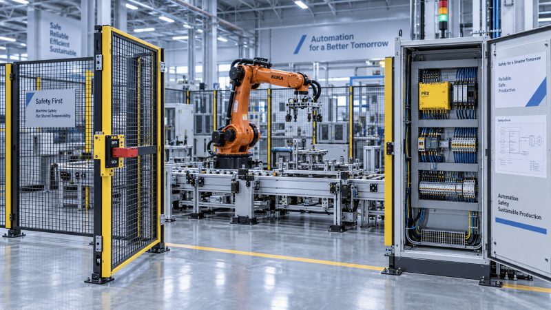
Industrial robot safety functions require validation when ISO 13849 is the chosen basis for demonstrating their functional safety. Whether that particular standard must be used depends on the applicable robot safety standards, legal framework, and project requirements. The robot arm alone does not define the scope: an integrated cell includes protective devices, control logic, drives, tooling, and other equipment whose combined behavior must be assessed.
A robot supplied with documented safety functions still needs application-specific verification after integration. Opening a gate, interrupting a protective field, or exceeding a monitored speed must produce the specified safe response throughout the relevant equipment. Supplier documentation supports that assessment, but it cannot establish whether the finished installation achieves its required performance levels or controls every identified hazard.
Robot safety standards and ISO 13849 answer different questions
The ISO 10218 series addresses industrial robot and robot application safety. It establishes requirements relevant to robot design, integration, protective measures, and verification. ISO 13849 addresses the safety-related parts of control systems: the parts responsible for detecting hazardous conditions and initiating or maintaining a safe response.
Within ISO 13849, Part 1 provides the framework for designing and evaluating safety-related control systems, including performance levels. Part 2 addresses validation through analysis and testing. The applicable editions and their relationship to the relevant robot standard should be established at the start of a project; requirements from different editions should not be combined without examining their compatibility.
Risk assessment, commonly structured using ISO 12100, establishes which hazards require reduction. Applicable machinery or robot standards can specify requirements for particular safety functions. Where a requirement is prescribed, selecting a lower target solely through an independent risk estimate is not an adequate justification.
IEC 62061 offers another functional safety framework for machinery control systems. Where applicable requirements permit that route, an ISO 13849 assessment is not automatically an additional obligation. The selected approach must cover the complete safety function and follow the integration rules of the chosen framework. Performance level and safety integrity level claims should not be treated as interchangeable labels.
The validation boundary follows the safety function
Consider a fenced robot cell with an access gate. The gate switch detects access, a safety controller processes the signal, and the robot controller executes a protective stop. If a conveyor or pneumatic clamp remains hazardous after the robot stops, the safety function must also address those hazards, or separate protective measures must control them.
The function therefore needs a precise specification. “Gate open stops robot” leaves important questions unanswered: which movements stop, how quickly they stop, whether stored energy remains dangerous, and what prevents unexpected restart. A useful specification identifies the triggering condition, affected equipment, safe state, response time, reset behavior, and operating modes in which the function applies.
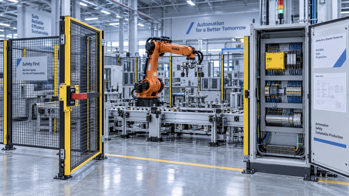
This boundary determines which evidence is relevant. A robot controller’s documented safety capability covers only the functions and interfaces described in its safety manual. External wiring, signal interpretation, safety network configuration, and connected machinery introduce additional conditions that the installed system must satisfy.
Validation also distinguishes stopping from maintaining a safe condition. Removing motor torque can prevent powered motion while leaving a vertical axis, suspended load, or pressurized actuator capable of movement. The required response might include controlled stopping, braking, restraint, or pressure management. The correct choice follows the hazard and the equipment’s behavior after the command.
Achieved performance level versus required performance level
The required performance level, commonly written as PLr, expresses the target for a particular safety function. The achieved performance level describes the capability of its implemented safety-related control system. These values have different origins: the target comes from applicable requirements and risk assessment; the achieved result comes from the design and supporting evidence.
A component marked with a high performance level does not transfer that rating to every circuit containing it. The complete function depends on the input devices, logic, output elements, architecture, diagnostic coverage, component reliability, and measures against common cause failures. Systematic failures, including incorrect programming and integration assumptions, also require attention.
For example, a dual-channel gate switch connected to suitable safety logic can still lose its intended fault tolerance if both channels are wired in a way that permits an undetected common fault. Likewise, output contactors need the appropriate monitoring and implementation conditions where their behavior forms part of the claimed architecture.
Category describes aspects of the control system architecture and fault behavior. It is one contributor to performance level, not a substitute for the full assessment. Statements such as “Category 3 installed” are incomplete unless reliability data, diagnostics, common cause measures, and other relevant requirements support the claimed result.
Calculation software helps organize this evidence, but its output depends on valid inputs. Component lifetime assumptions, switching frequency, diagnostic measures, and subsystem boundaries must match the installation. A calculated performance level cannot establish that the safety program selects the correct stop function or that the gate is physically positioned safely.
Calculation and testing expose different failures
Validation combines analysis with tests selected to confirm the safety requirements. Analysis establishes whether the architecture, reliability assumptions, fault treatment, and integration conditions support the claimed performance. Testing establishes whether the implemented equipment responds as specified under relevant operating conditions.
A successful gate-opening test demonstrates one observed response. It does not prove adequate fault tolerance, reveal every dangerous failure, or confirm that reliability assumptions are correct. Conversely, a satisfactory calculation does not demonstrate correct wiring, timing, reset logic, or software configuration.
Useful test cases arise directly from the safety specification. A gate interlock assessment can include opening the gate during automatic operation, attempting a start with the gate open, restoring the protective condition, and examining specified fault responses. Fault simulation requires a controlled method that avoids introducing an uncontrolled hazard.
Reset and restart deserve separate treatment. Where a manual reset is required, restoring the gate or releasing an emergency stop should leave the system in the specified condition awaiting deliberate action. Reset acknowledges restoration of the protective conditions; its intended relationship to a subsequent start command must be defined and verified.
Operating modes can change the applicable protective measures. Automatic production, teaching, setup, and recovery can use different combinations of interlocks, enabling devices, speed limits, and permitted motion. Testing only automatic operation leaves those transitions and alternative modes unexamined.
Stopping performance can change the installation decision
A control system can achieve its required performance level while the physical protective arrangement remains inadequate. A light curtain positioned too close to the hazard can permit access before hazardous motion has stopped. Performance level addresses the reliability of the safety function; protective distance also depends on response and stopping behavior.
Total response includes sensing, signal transmission, logic processing, output response, and machine stopping time. Measurements must represent the relevant application conditions. Payload, robot pose, speed, tooling, and movement direction can affect stopping behavior, so a convenient unloaded test is insufficient when production creates a more demanding condition.
For an interlocked gate, the time needed to reach the hazard matters. If hazardous motion continues after access becomes possible, guard locking or another protective arrangement may be necessary. A signal confirming “stop requested” is different from evidence that access is safe.
These relationships explain why relocating a scanner or changing a robot’s operating envelope can require renewed assessment even when the safety controller remains unchanged. The control function and the physical installation must work together to satisfy the protective objective.
Conventional robot cells and collaborative applications
A collaborative robot does not remove the need for safety validation. Its built-in functions provide capabilities that must be configured and assessed within the application. The task, tool, workpiece, nearby structures, and accessible movements determine whether the intended collaboration is safe.
In a fenced cell, validation often concentrates on access protection, stopping, mode selection, and prevention of unexpected motion. A collaborative application can place greater emphasis on monitored speed, separation, limiting contact forces, or restrictions on position and motion. Each implemented safety function still needs a defined target and supporting evidence.
Power and force limiting illustrates the distinction between control validation and application assessment. A validated limiting function does not establish that every possible contact is acceptable. A sharp tool, small contact surface, trapped body part, or heavy workpiece changes the consequences of contact. Application-specific evaluation must address those conditions.
Similarly, speed and separation monitoring requires evidence for sensing coverage, detection limitations, response time, and the stopping behavior used to establish protective separation. A valid sensor rating cannot compensate for an obscured detection area or an unsupported assumption about robot deceleration.
What makes the validation record usable
A defensible record connects each hazard to a protective measure and each safety function to its requirements, implementation, and validation results. It should make the relationship between the required performance level and the achieved result traceable without requiring assumptions about what was tested.
The supporting material includes relevant circuit diagrams, component safety data, reliability calculations, fault analyses, and the conditions attached to subsystem claims. Test records need identifiable configurations, test conditions, expected responses, observed results, and any unresolved deviations. Safety software and parameter versions matter because later changes can alter the behavior that the original evidence established.
Responsibility for robot subsystems and the integrated application can be distributed across different parties. A subsystem report is useful only when its boundaries and conditions are explicit. The complete installation still needs an accountable validation process, with the competence and independence required by the applicable framework.
Changes should trigger a review of the affected evidence. Replacing an interlock with a different device, modifying safety logic, increasing payload, or changing pneumatic behavior can affect different parts of the assessment. A like-for-like replacement might require focused verification; a changed safety function requires reassessment of its requirements and implementation.
The practical acceptance criterion is a traceable result: every required safety function has an established target, an implementation supported by suitable evidence, and validation that confirms the specified behavior in the installed application. Until those links are complete, a robot’s individual safety rating leaves the cell’s safety claim unresolved.
Recommended News
- 2026/10/24Car Spare Parts: How to Check Fitment and Avoid Ordering the Wrong PartOrder car spare parts with confidence. Learn how to verify VINs, OEM numbers, and fitment details to avoid costly mistakes and choose the right replacement first time.
- 2026/10/23How Do You Select a Motion Control System for Synchronized Axes?How do I select a motion control system for synchronized axes? Discover key timing, feedback, and performance checks to choose confidently and reduce costly integration risks.
- 2026/10/23Integrating End-of-Line Sortation with Packing Stations and Conveyor ControlsOptimize end of line sortation with coordinated packing stations and conveyor controls. Learn how to prevent bottlenecks, improve routing accuracy, and handle exceptions reliably.